User Guide
General user information and details about the hardware.
Hardware
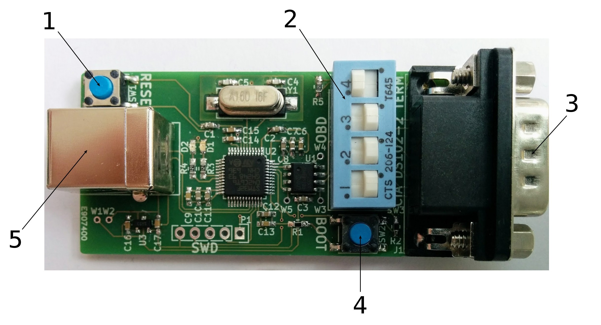
- reset button - Resets the micro controller when pressed.
- DIP switches - Switch 4 (top one) is used to add a 120 ohm termination resistor to the CAN bus. When it is set to the left as in the image, no termination resistor is added. When set to the right, the termination resistor is added. “TERM” is printed between the DIP switches and the DB9 connector to indicate this. Switches 1-3 (bottom ones) are used to select the type of CAN DB9 cable connected. When they are to the right as in the image, a CiA DS102 cable is selected. When they are to the left, a US style OBD-II to DB9 cable is selected. Note the difference in pinout. “CiA DS102” and “OBD” are printed next te the DIP switches to indicate this. It is important that all of these three switches are on the same side and not for example two to the left and one to the right. Only change them when the device is unpowered.
- CAN DB9 connector - Connect to the CAN bus using a CiA DS102 or standard OBD-II to DB9 cable.
- boot button - Sets the micro controller in bootloader mode when used with reset.
- USB 2.0 type B male connector - Powers the device and connects it to the host via full speed USB.
LED indicators
- green blink - interface down
- green steady - interface up
- red blink - bus error
- red steady - firmware error
Firmware update
- download the latest firmware
- enter bootloader mode
- flash the firmware
Download the latest version of the firmware from github. Make sure to include the third party libraries. Compile it by going into the root directory and typing make on the command line. Put the device in bootloader mode by holding the BOOT button and then pressing the RESET button. All the LEDs should be turned off. Then flash the device by typing make dfu on the command line. Finally press reset to return the device to application mode.